

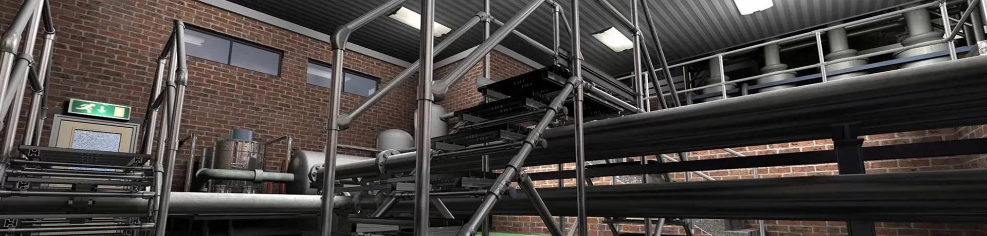
 Conveyor Safety Railing Systems
Around an industrial conveyor, a safety railing system creates a physical boundary around the places where people can reach a hazard or enter a maintenance area. In project terms, the useful unit is not a length of fence. Functionally, it is a surveyed run with a stated purpose, controlled openings, a fixing path and an acceptance record.
Begin at the conveyor. During the survey, mark transfer points, drive assemblies, return-side rollers, discharge ends, crossovers, service aisles and any raised walking surface beside the line. Only after that should the team decide what each rail run must do. Because a run that keeps pedestrians out of a normally closed zone is a different problem from a guard that prevents fingers entering a nip point, or a guardrail at the edge of a raised walkway. Similar-looking posts and rails may serve unrelated duties. Their duties are not interchangeable.
This page is for project and plant teams specifying fixed conveyor perimeter railing. That guidance explains where the system belongs, how to plan access, what must be coordinated with machine safety and lockout, what information the fabricator needs, and how to accept the installed arrangement. Page boundaries prevent a rail drawing from replacing the conveyor manufacturer, a machine-safety specialist or a local risk assessment.
Start with a conveyor walkdown
In practice, a drawing review alone misses what happens on the floor. Before drawing conclusions, walk the line when it is stopped, then observe normal operation from a safe position. From the designated observation point, record the route a worker takes to clear a jam, remove a package, inspect a belt, reach a drive or clean a transfer table. Every narrowing of the walkway matters, as do cart waiting points and tool storage.
Prepare a simple zone list:
- Product transfer and loading points where hands, tools or clothing can reach an in-running nip.
- Return rollers, chains, belts, shafts and drive assemblies that may be exposed below or beside the carrying surface.
- Curves, merges and diverters with changing clearances.
- Discharge ends where product can fall or swing.
- Crossovers and man doors used during normal production.
- Maintenance panels, inspection covers and removable sections.
- Raised catwalks, platforms or openings beside the conveyor.
- Emergency exits, fire equipment, control panels and isolation devices that must stay reachable.
For each zone, write who approaches it, how often, with what tools or PPE, and what movement could cause injury. Any rail run with no named exposure is likely decoration. Whenever a proposed run blocks the only safe maintenance route, expect it to be bypassed.
Along the approach, record the safe side as well as the exposed side. Beside a busy line, a fixed fence may keep a visitor away from the outside while leaving the operator side open. From the production floor, a gate may appear convenient but prove dangerous to open from the conveyor side. Before hardware selection, mark the safe operating side on the drawing.
Separate four jobs that look alike
What is this run meant to control?
The answer changes the evidence, opening logic and acceptance basis. It also prevents one railing line from being asked to do four jobs.
Control repeated pedestrian access around a surveyed conveyor zone. Prove the route, opening schedule and normal closed state.
Conveyor projects often use one word for several controls. Set the vocabulary before fabrication.
| Intended job | What it controls | What the project must prove |
|---|---|---|
| Perimeter separation | Repeated pedestrian or vehicle-adjacent access to a defined work zone | The route, access points and normal closed state |
| Machine guarding | Contact with moving machine parts, including point-of-operation and power-transmission hazards | Reach, opening geometry, guard construction, fixing and the safety-control logic |
| Fall protection guardrail | A person falling from an open walking-working surface edge | The applicable fall-protection basis, geometry, load path and anchorage |
| Handrail or route support | Balance and guidance along a stair, ramp or access route | The walking route, grip and transition requirements |
29 CFR 1910.212 states that machine guarding must address hazards such as the point of operation, ingoing nip points, rotating parts, flying chips and sparks. The same rule says a point-of-operation guard must prevent any body part from being in the danger zone during the operating cycle. Such a rail can support that aim, but it is not automatically a compliant machine guard. Openings, reach and the machine's operating cycle still need review.
Power transmission adds another layer. 29 CFR 1910.219 covers belts, pulleys, flywheels, friction drives and projecting parts with specific conditions and exceptions. Merely enclosing the largest part does not accept a frame around a drive assembly.
At height, use the fall-protection requirements that actually apply to the walking-working surface. In covered U.S. general-industry work, 29 CFR 1910.28 triggers fall protection at four feet above a lower level. When a guardrail is selected as the solution, 29 CFR 1910.29 gives the relevant criteria: a top edge at 42 inches, plus or minus 3 inches; a 200-pound top-rail force criterion; and a 150-pound intermediate-member criterion. Neither set becomes a conveyor guard opening or an impact rating. They apply only to the system being accepted as a fall-protection guardrail.
Write the duty on the drawing. Labels such as "conveyor fence" are too vague for fabrication, inspection or a future modification. Use "perimeter separation - normal access closed except maintenance panel MP-3" or "fall-protection guardrail at a raised service walkway." Sharp duty labels prevent a low separator from being treated as a guard and prevent a fall guardrail from being loaded like a vehicle barrier.
Design the route before the rail
Across the floor plan, a conveyor railing system works best when the route is already clear. Begin with the walking path. People should not need to step around a post, duck under a brace or cross a moving line because the fence was added after the aisle was painted.
Keep emergency and maintenance access visible. Shortcut-sealing rails may improve separation. Blocking-only rails fail the decision when they close the only safe route to an isolation device, fire extinguisher or exit.
Apply the full movement envelope around the line to avoid a false fit. Within this envelope are the widest product, the maintenance cart, the tools a technician carries and the space needed to remove a panel. Unless proven otherwise, check whether doors, gates and hinged sections can open without hitting a control box or blocking an adjacent aisle.
Then ask whether the rail can be omitted from a section. A conveyor path does not need a continuous fence if a wall, machine enclosure, guard or approved layout already creates the boundary. Each design should record that adjacent structure as part of the boundary rather than adding redundant steel for visual symmetry.
Give every opening a normal state
Name the state before choosing hardware
Every opening needs an operator, a safe side and a return check. The hardware follows that decision.
The opening remains in its defined closed state until an authorised transfer or maintenance task begins.
Most conveyor rail failures in service start at an opening. The gate may exist, but no one has defined when it stays closed. A removable panel may be stored against the conveyor. A maintenance door may be tied open during a shift. The result is a correct-looking closed layout that is normally open.
Create an opening schedule:
| Opening type | Normal state | Critical information |
|---|---|---|
| Transfer gate | Closed when no transfer is active | Who opens it, safe-side operation, how it closes and who restores it |
| Maintenance gate | Closed and controlled until the task starts | Isolation method, task owner, tool access and restart check |
| Hinged guard section | Closed during production | Hinge direction, latch, support in the open position and return check |
| Removable panel | Installed whenever the line can operate | Storage location, lift aid, alignment marks and approval to remove |
| Inspection window or opening | Closed or fixed according to the machine-safety design | Reach, sightline, cleaning method and approved opening geometry |
| Crossover | Closed except for use | Traffic rule, sightline, non-slip approach and conflict with vehicle routes |
Operationally, the schedule should use plain states: production closed, authorised use, maintenance open and returned to service. If an opening has none of these states, the design is incomplete.
Never assume a gate closes the hazard just because it is attached. Any gate with no latch, removable panel with no storage control or hinged frame that can swing into the operator's escape path creates a new problem. The opening hardware must be operable from the safe side and must not create a shear, crush or snag point of its own.
Coordinate maintenance with hazardous energy
Conveyor maintenance access is an interface with the site's energy-control procedure. 29 CFR 1910.147 applies to covered servicing and maintenance where unexpected energisation, start-up or stored-energy release could cause injury. Removing or bypassing a guard, or placing a body part into the point-of-operation danger zone, can bring the task into that scope.
Designers do not need to write the lockout procedure. The design must, however, leave room for it. Inspect the location of the disconnect, isolation point, lockout hardware, verification point and stored-energy release. Ensure that the guard opening gives access without forcing the technician to stand in an unsafe position.
When the maintenance task is routine, repetitive and integral to production, the site may use an alternative protective measure under the applicable rule. That decision belongs to the machine owner and safety specialist. It should be documented before a sliding panel, light curtain, interlock, hold-to-run control or local procedure is treated as the answer.
Although a fixed rail can support maintenance safety, steel cannot certify the restart logic. If a gate is interlocked, the interlock and control system require machine-safety review. Padlocked gates must still fit the energy-control plan. A padlock on a gate is not automatically lockout of the drive.
Cross-reference the opening schedule with the maintenance procedure. For each opening, note which task uses it, what must be isolated, what verification is performed and what check allows production to resume. This is the connection between steel and operation.
Resolve reach, openings and standoff distance
Avoid choosing an opening size from a catalogue without checking the conveyor hazard. Opening geometry depends on what can pass through it, how far the person can reach, the location of the danger zone and the operating cycle.
Compare the guard location with the moving parts on the machine and elevation drawings. Include guard depth, tube or wire spacing and the possibility of reaching through, over, under or around the frame. Ask whether clothing, gloves or tools can snag. Measure the distance from the opening to the nip, not only the visible fence height.
Some projects need a solid or mesh guard to stop reach. Some need a perimeter rail at a safer standoff. Some need a fixed guard at the nip point and a separate rail for route separation. The correct answer may combine controls. Treating every section as one rail product makes the layout less precise.
Changing product size, guide position or transfer configuration creates a moving design problem. Record the range of normal settings. A fence that clears the current guide may interfere after a product change. A removable section that is safe for one package size may expose a larger opening during another run.
When a dimension cannot be verified from the conveyor documents, mark it for field measurement. Where the project needs a specific design basis that HULK has not been given, use this sentence in the project correspondence: Contact us for details.
Trace the structural path
Draw the load path from the top member to the building or supporting structure. For a person-fall guardrail, the accepted criteria and project design determine the design load. For a perimeter rail, normal contact, leaning, cart impact or another identified exposure may create a different demand. Do not borrow the force value from one system for the other.
Begin with the support condition. A post fixed to a raised steel structure, a slab, a freestanding base or the conveyor frame does not have the same load path. The project team must identify the supporting element, its condition and the person responsible for approving the connection.
Then review the rail frame itself: posts, horizontal members, joints, base plates, fasteners and any brace or return. The fitting that looks neat on a sample panel may not suit the actual post spacing, base detail or opening geometry. The same is true for the anchor. A visual check of a tightened bolt is not a structural approval.
Coordinate interfaces before fabrication:
- conveyor frame and support locations;
- building columns and slab edges;
- cable trays and pneumatic lines;
- controls, sensors and emergency stops;
- doors, levelers and adjacent machines;
- drainage, cleaning equipment and traffic routes;
- access for the maintenance lift or lifting device.
If the rail is attached to the conveyor, decide who owns that connection and whether the conveyor manufacturer permits it. If the rail is independent, keep the base and anchors out of the pedestrian envelope. If the two structures move differently, the joint needs review rather than a field cut.
No universal post spacing, anchor capacity or tube size is published here. Those details belong in a project drawing and a verified connection design. Where they are not yet available: Contact us for details.
Select the finish from the environment
A conveyor runs through the environment, so the environment belongs in the purchase description. Dry distribution centres, wash-down food lines, humid processing rooms, coastal plants, freezers and abrasive bulk handling areas expose the rail to different conditions.
Determine the cleaning method and chemicals before selecting a finish. A coating suitable for a dry warehouse may fail to meet the cleaning basis in a wash-down room. A damaged coating at a base plate or field cut needs an approved touch-up route. Colour is not a complete finish specification.
Look at trapped debris. Horizontal ledges, open tube ends and base details that collect product can create hygiene and inspection problems. Smooth surfaces and accessible joints help, but the correct detail depends on the service environment.
Inspection should guide the finish choice as well. A dark or low-contrast rail may hide coating damage under poor light. A rail with many small joints may be difficult to clean. The maintenance team should be able to see a defect before it becomes a repair.
Plan the installation sequence
Sequence reduces rework. Start with the surveyed route and a datum on site. Mark post locations after checking slabs, embedded steel, conveyor supports and underground services. Do not drill the first anchor from a scaled drawing without confirming the actual structure.
Install the first run as a reference. Verify vertical alignment, top-member line, base contact and opening position. Operate the gate or removable section from the safe side before completing the rest of the line.
Then install the controlled openings and test them through the full travel. If a hinge binds or a gate swing enters a walkway, correct the layout before continuing. The opening is not a late accessory; it changes the geometry and use of the run.
After the frame is in place, inspect every interface: conveyor clearance, electrical equipment, controls, drainage and routes. Record cuts, shims, field-drilled holes and deviations from the drawing. Field changes can alter the load path or create an unplanned reach opening.
Finish with the handover walk. Move along the complete route in both directions. Operate each opening. Observe the normal state. Ensure that the rail is visible and usable, that emergency access remains clear and that no temporary bracing has been left in the route.
Build an inspection record that can be repeated
Mark the evidence collected in this session
This local progress control does not submit data. The export below is preparation for the project record.
At first inspection, define the baseline for the asset. It should not be a one-page "installed correctly" checkbox. A later inspector needs to know what was measured, where the opening was, which structure carried the post and what defects were accepted.
Include these fields in the record:
- Drawing or approved layout version.
- Run identifier and location.
- Intended duty and applicable basis.
- Post and anchor references.
- Opening identifiers and normal states.
- Finish and service environment.
- Field deviations.
- Photographs from named viewpoints.
- Installation date and responsible people.
- Next inspection trigger or interval from the site's procedure.
| Record group | Evidence to retain | Why it matters |
|---|---|---|
| Identity | Run ID, drawing version and location | Prevents a later check against the wrong layout |
| Duty | Intended function and applicable basis | Separates perimeter, machine and fall-protection duties |
| Access | Opening IDs, normal states and task owner | Shows whether the installed control remains usable |
| Load path | Post, base, anchor and support references | Connects visible steel to an approved structure |
| Condition | Measurements, photographs, defects and repairs | Makes the next inspection comparable |
Inspect the items that can change the function:
- rail continuity and end conditions;
- post alignment and movement;
- base-plate contact and anchor condition;
- fitting or fastener loosening;
- damaged or removed sections;
- opening operation and latch condition;
- objects stored against the rail;
- blocked emergency or maintenance access;
- coating damage and corrosion at the base;
- conveyor clearances after maintenance or product changes.
Where damage, movement or a missing member affects a controlled opening, isolate the affected use until the repair is reviewed. A clean coat of paint over a moved post does not restore the load path.
Treat recommissioning as a new check
Maintenance and product changes disturb conveyor guarding. A technician may remove a panel, alter a guide, replace a roller or add a cable tray. Before production resumes, confirm that the opening was restored, the fasteners are present and the rail has not become an obstruction.
Maintenance records should include the restart check. It need not be long. It must answer four questions:
- Is each opening in its defined normal state?
- Is each guard or rail section that was removed now installed?
- Is the affected route clear of tools and temporary supports?
- Has any field change altered reach, clearance or the support path?
After a major modification, repeat the route walk. A new conveyor branch may create an opening into the old protected zone. A taller product may project over a rail. A new control panel may make a maintenance gate unsafe to use.
Prepare a usable RFQ pack
Prepare the project handoff
Select the evidence available. Nothing is sent or stored by this page.
An RFQ that only says "supply conveyor safety rail, 30 metres" leaves the supplier guessing. The price and fabrication route can change with duty, openings, finishing, supports and installation responsibility.
Send:
- plan and elevation drawings with north or line direction;
- conveyor type and hazard-zone marks;
- the intended duty of each run;
- opening schedule and normal states;
- maintenance-task descriptions;
- environment and finish requirements;
- supporting-structure details;
- connection ownership and approval route;
- required installation and inspection documents;
- quantity, project location and required delivery basis.
Identify the items still open. If the conveyor frame or slab is not confirmed, state that. If the gate must be interlocked, identify the machine-safety owner. If the rail is part of a fall-protection system, give the applicable basis rather than a generic height.
HULK can review a dimensioned layout and the visible interface information. Where the project has no approved capacity, torque, test method or finish basis, the answer will remain Contact us for details. rather than an invented number.
Frequently asked conveyor railing questions
7 questions shown
Is conveyor safety railing the same as a machine guard?
No. A perimeter rail can stop a person reaching a controlled zone, but machine guarding must address the specific moving hazard and the way a person can reach it. 29 CFR 1910.212 treats point-of-operation, nip-point and rotating-part hazards as machine-guarding problems. If the rail is part of that solution, its opening geometry, construction and fixing still need approval for the machine duty.
Does every conveyor need a perimeter fence?
No. A conveyor in a guarded enclosure, behind an existing wall or outside the normal walking route may need no additional perimeter fence. Add rail only where the surveyed layout leaves an exposure that requires physical control. A rail with no named exposure adds cost, restricts access and may create a false sense of completeness.
Should a conveyor fence be 42 inches high?
A 42-inch top edge is the U.S. general-industry guardrail criterion stated in 29 CFR 1910.29 when the rail is serving as a covered fall-protection system. It is not the universal height of a conveyor barrier or a machine guard. Select the rail geometry from the duty, applicable rule, risk assessment and project design.
Can a locked gate replace an interlock?
A mechanical lock can control who opens an opening. It does not perform the function of an interlocked guard or another machine-safety device. If the machine must stop or enter a safe state when the opening is used, the control architecture requires a separate machine-safety review.
Should the rails be mesh panels or open pipe rails?
Use the hazard and task to decide. Mesh or solid guarding can block reach and small parts from passing into a dangerous zone. Open pipe rails can preserve sightlines and separate a walking route. The choice also depends on cleaning, accumulation, machine visibility and the conveyor manufacturer's requirements.
What information is needed for a conveyor railing quotation?
Send a plan and elevation, hazard-zone marks, the intended duty of each run, the opening schedule, support details, environmental exposure and quantity. Mark any measurement or connection that is still unconfirmed. That information changes the frame, fixings, finish and approval route.
How often should conveyor guarding be inspected?
This page does not set one interval. Use the site procedure, applicable local requirements, manufacturer instructions, hazard, environment and event history. Add a check after any impact, guard removal, conveyor modification, product change that alters reach, or repair.
Common failure modes
Failure one is a rail with no duty. It looks continuous, but no one can say whether it is separating a route, guarding a nip or protecting an elevation.
Failure two is an opening without a normal state. The gate is designed, installed and immediately tied open because the transfer workflow does not fit the rail.
A third problem appears when a fence is treated as the entire machine-safety solution. Reach, interlock, energy isolation and restart remain unresolved.
One common error fixes the rail to a convenient surface without a load path. The post and base appear tight, but no one has approved the structure or the connection.
Number five is a field modification that creates a new gap. A cut for a cable tray or a removed panel can change the guard opening without changing the drawing.
Another failure starts with a finish selected from a colour sample. Cleaning chemicals, humidity, salt or abrasive dust then attack the rail at the base and joints.
Finally, an acceptance record that contains only ticks cannot show what was measured, where the opening was or what repair occurred.
What acceptance should leave behind
Archive the final record so another person can understand the system without asking the installer. Keep the approved drawing, duty schedule, opening schedule, interface notes, connection references and as-built photographs together.
At the physical check, operate every opening. Confirm that open and closed states are visible. Walk the pedestrian and maintenance routes. Inspect access to isolation points and emergency equipment. Measure the geometry that belongs to the selected duty. Trace the post and anchor path to the referenced supporting structure. Record any deviation.
At a conveyor perimeter, the strongest evidence is not the number of metres supplied. It is the proof that every reachable zone has a named control, every opening has an owner and every fixing point belongs to an approved load path.
Under normal operation, the rail should make its state obvious. People should not have to guess whether a panel is missing, a gate is tied back or a section is waiting for repair.
Final decision
Specify conveyor safety railing as a system. Start with the conveyor exposure, assign one duty to each run, control the openings, coordinate the maintenance and energy-isolation interface, verify the support path and record the installed arrangement.
Choose the HULK Metal machine-guard article when the project needs to understand pipe-fitting assembly. Select this page when the project needs a complete conveyor perimeter and access-control decision. Engage a qualified machine-safety or structural review where the design depends on reach, safeguarding logic, fall protection or anchor capacity.
Ready drawings let a fabricator identify every run, a maintainer operate every opening and an inspector repeat every check. That is the standard the railing should meet.
Related project pages
Continue with the broader industrial or warehouse system when the conveyor exposure is only one part of the layout. Use the installation article for roof-edge work rather than applying conveyor assumptions to a roof.
Build Business With HULK.